Wednesday, October 24, 2012

Interfacing between the gameboy and arduinoboy

I don't know about you but in Australia its quite difficult to find a DMG link cable. On ebay there doesnt seem to be any aftermarket cables available so any original cables which do come up on ebay can cost up to $40. To get around this the cables I used are GBA,GBP link cables as they are usually < $5 AU on ebay. I also discovered so additional benefits to this method which I'll cover below.

This is the link cable that i've gone with and its pretty good. Its cheap, it works, it allows daisy chaining and you can choose the colour it comes with.


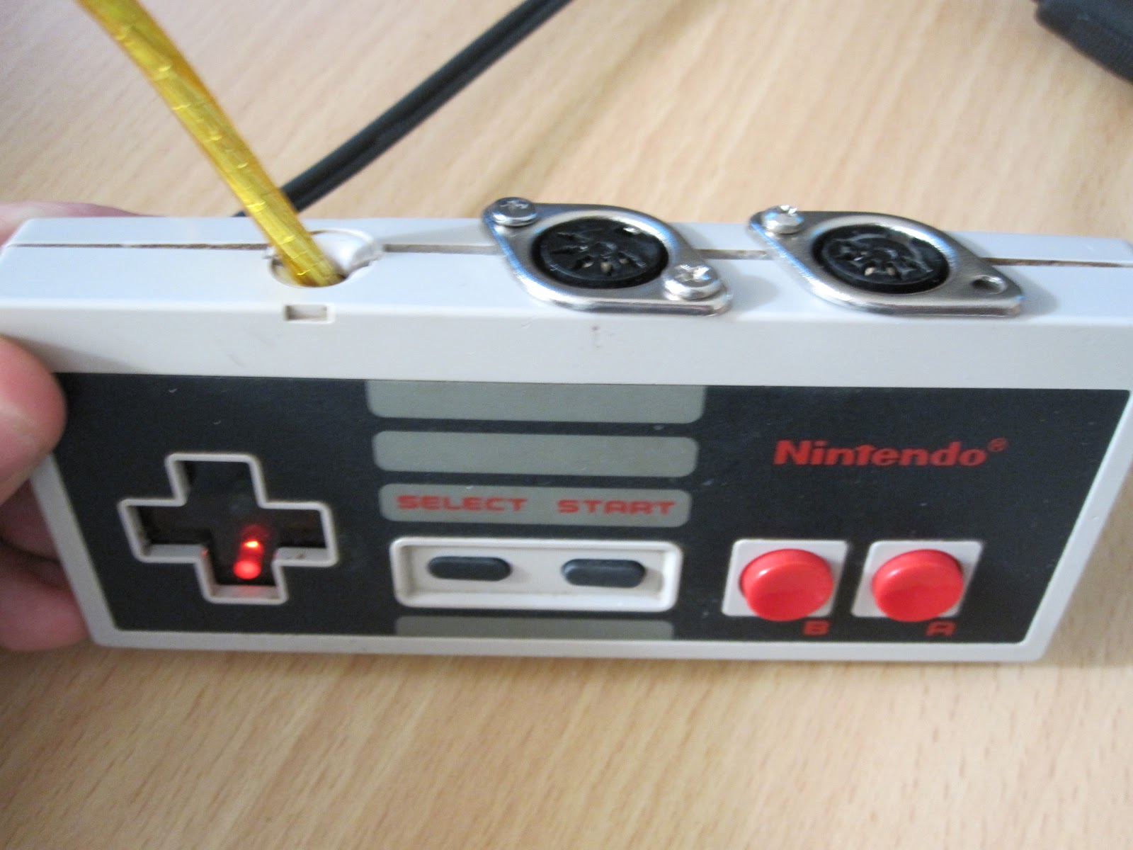
The first thing you'll need to do is remove the link cable female connector on the gameboy, this is pretty straight forward, there are 8 pins which need to be desoldered to remove the connector (as shown below in RED).


Next, cut the wire in half, expose the wires on both ends and tip each wire with solder. One thing to note is that when the link cable is connected the wire colours will not correspond so its a good idea to connect the cable together using the linkcable connectors and performing a continuity test to figure out which wire colours correspond to which. Once this is done simply solder the wires to the arduinoboy and the gameboy ensuring that the pins correspond correctly. The picture above describes the which pins should correspond to what on the arduinoboy (in yellow).


 I would also suggest gluing the cable to the gameboy to prevent force on the solder joints. I used a hot glue gun....


At this stage you should have the gameboy and arduinoboy happily communicating with one another. However the neat thing i discovered is that with this method you can also daisychain multiple gameboys on the same arduinoboy if you want to sync multiple gameboys. THe picture below shows 2 gameboys which are simultaneously synced with Ableton using one arduinoboy. Another neat trick is if you use mGB on both gameboys you can set one gameboy to play one octave higher as an easy method to achieve chords.


THe process for adding wiring up another gameboy this is exactly the same. Simply cut the link cable in half, perform a continuity test on the wires to figure out which wire colours correspond to which and solder them to the gameboy just the same as before. Note that the wire colours will not correspond with the other gameboy so another continuity test is needed.

I might post up a video later...

Hope this helps and let me know if you have any questions or feedback... cheers

Monday, October 15, 2012

Arduinoboy NES controller

So if you've seen either of the videos i posted a few weeks ago, you'll notice the arduinoboy fit snug inside a NES controller. When I was initially building my arduinoboy I was unsure how i was gonna enclose it. Luckily there is no shortage of retro controller in my cupboard so an NES controller seemed appropriate.


First step I would recommend is to remove the original dpad and try also removing as much of the internal plastic fittings inside the NES as you can because you will most likely need all the space you can get. You'll notice that the LEDs are aligned with the dpad which I thought was cool as it cycles up,down,left,right for each beat. I've also arranged the mode button for the arduinoboy to line up with the NES select button  :)


Theres nothing special with the select button really, its just a pushbutton under the select button. The dpad however took a bit of trial and error as its easy to underestimate how little space is in there.  It consists of 5 Flat top Mini LED's faced outwards with  a polarisation filter between the LED's and front controller plate. The Flat top Mini-LED's seemed to be the only type of led I managed to fit with the polarisation filter in place. In the end its up to you how you want to mount it, just be sure the leds are wired to the correct pins on the arduino for the cycling effect. From memory the dpad direction LEDs are mapped to the arduinoboy as follows (please dont hold this against me if im wrong)

Left = D8
Down = D9
Right = D10
Up = D11
Middle = D12
(Unfortunately the status LED has to be sacraficed... oh well)

If you decide to use a polarisation filter to go over the LEDs you may also want to scratch it up a bit to disperse the light more.... again up to you :)


The tightest fit by far has to be the DIN connectors at the top. Kudos if you can fit smaller DINs than what I used but for the type I used the diameter of the hole had to be the entire height of the NES controller and some. If you look carefully at the photo below you'll see a groove made using a dremel to thin out the thickness of the plastic.... it was that close.


Friday, October 12, 2012

Cutdown GB sound mod

So the prosound mod by Trash80 is a pretty fundamental for any gameboy modder. However if space is a big issue for your gameboy, this post may be helpful if you're trying to cut back on as much as possible. In this variation of the Trash90 prosound mod we will be modding a gameboy for the extra DB out of the 3.5mm stereo jack as you would normally but in the process the pcb connected to the 3.5mm output will be completely removed. The only disadvantage with this technique is that you sacrafice the ability to output to the gameboy internal speaker but this just means you can take out the speaker also for more room!

The following three pictures below show how the prosound mod is usually wired up.


In our variation we will firstly remove the audio output PCB from the gameboy by unscrewing the screws and chopping the 3 black and 1 white wires as shown above. Once the audio output PCB has been removed we will now desolder the 3.5mm headphone jack from the pcb and reattach the 3.5mm headphone jack back into position without the PCB as shown below. Finally, wire up the headphone jack as shown below such that it connects to the red and green wires post-pot pins on the PCB and the white wire goes to ground.


As an additional step, its probably helpful to remove the internal speaker also as that will no longer be of any use and this can be done simply by chopping the two speaker wires.

Hope this helps and happy modding :)